

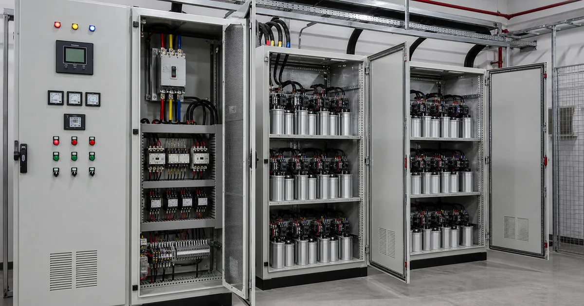
Power Factor Controller Working Principle: APFC Panel Explained
- Published 04 Aug, 2026
- 8 min read
A power factor controller measures reactive demand and switches capacitor stages in an APFC panel. Correct sensing, step sizing, protection and harmonic review are essential for reliable correction.
What is a power factor controller?
A power factor controller is an electronic relay that monitors voltage and current to estimate the phase relationship and reactive-power requirement. It commands capacitor contactors or thyristor switches in an automatic power factor correction panel. The aim is to keep power factor near the configured target as inductive loads change.
The controller is one component of the APFC system. Current transformers, capacitor steps, switching devices, detuned reactors where needed, breakers, ventilation and wiring determine whether the complete panel performs safely.
How APFC panels work
Motors and transformers draw reactive current. The controller compares the measured condition with its target and adds capacitor stages when lagging reactive demand increases. It removes stages as demand falls, using programmed delays to prevent unnecessary rapid switching.
Steps may be equal or arranged in smaller and larger kvar combinations. Good step design gives enough resolution at light load while providing full correction at peak demand. Incorrect current-transformer polarity, ratio or location can cause over-correction or failure to respond.
Why poor power factor increases electricity cost
For the same useful kW, a low power factor requires more current. Higher current increases cable and transformer loading and resistive loss, and it can reduce capacity available for additional equipment. Utilities may apply penalties or demand charges according to the applicable tariff and metering method.
APFC can reduce reactive current drawn from the utility when designed correctly. It does not directly reduce the real energy consumed by a motor doing the same work, so savings claims should separate loss reduction, capacity release and avoided tariff penalties.
Power factor controller vs capacitor bank
A capacitor bank supplies reactive power. The controller decides how much of that bank should be connected at a given time. A fixed bank has no automatic controller and can over-correct when the load falls. An APFC panel combines measurement, logic and switched capacitor stages.
Rapidly changing loads may need thyristor switching or a static var generator rather than conventional contactors. Harmonic-rich networks may require detuned banks or other solutions because ordinary capacitors can resonate and overheat.
Where APFC panels are used
Factories, textile mills, hotels, hospitals, shopping malls, offices and water systems use APFC panels where motors, transformers, chillers, compressors and pumps create changing inductive demand. Panels can be installed at the main distribution board or closer to large load groups.
The installation point affects what the utility meter sees and how current flows within the plant. Central correction may not unload upstream internal feeders in the same way as distributed correction, so the single-line diagram should guide placement.
How to choose APFC panel capacity
Use measured kW, present power factor and target power factor to estimate kvar. Logging over representative shifts reveals minimum, average and peak reactive demand. Review transformer capacity, generator operation, load growth, harmonics and switching frequency before selecting steps.
A harmonic survey is important where VFDs, UPS systems, welders or rectifiers are significant. Adroit can review measured demand and network conditions before recommending conventional, detuned or faster dynamic correction.
Capture several operating periods because shifts, seasonal production and generator operation can change reactive demand. Record kW, kVA, kvar, voltage, current and harmonic distortion at the proposed connection point. The design review should cover capacitor voltage rating, reactor tuning, switching method, step sequence, enclosure cooling and fault protection. After commissioning, verify stage operation at low and high load and keep the controller settings with the panel records. This gives maintenance staff a clear baseline for inspecting capacitors and investigating future power-factor changes. Periodic review is especially important after adding drives, welders or large motors because the original step plan and harmonic conditions may no longer represent the plant. Trending stage operating hours can also expose failed capacitors or an unsuitable switching sequence. Inspect terminals and ventilation under a documented maintenance schedule.
- Measure power factor and kvar by shift
- Verify CT ratio, polarity and location
- Choose practical capacitor step sizes
- Review harmonic distortion and resonance
- Coordinate breakers, contactors and ventilation
FAQs
What is power factor controller?
It is a relay that measures the electrical load and automatically commands capacitor stages to maintain a selected power-factor target.
How does APFC panel work?
It connects or disconnects capacitor steps as reactive demand changes, based on measurements from voltage and current-transformer inputs.
Can APFC reduce electricity penalty?
It can reduce penalties related to poor power factor when correctly sized and maintained under the applicable utility tariff.
What is the difference between APFC and capacitor bank?
A capacitor bank supplies reactive power; an APFC system adds a controller and switching stages so correction follows changing load.
Which industries need power factor correction?
Facilities with motors, transformers, pumps, compressors, HVAC and other inductive loads commonly require power-factor review.
Related Products and Solutions
Related Articles
Need help choosing the right solution?
Contact Adroit Power Systems for stabilizers, UPS systems, power quality correction, solar UPS and industrial backup power guidance.